Timer And Contactor R Relay Diagram - Solved True False 1 Point Each 1 Three Phase Motors Mu Chegg Com / Using an ohmmeter, test between 2 testing compressor contactor.
Timer And Contactor R Relay Diagram - Solved True False 1 Point Each 1 Three Phase Motors Mu Chegg Com / Using an ohmmeter, test between 2 testing compressor contactor.
Timer And Contactor R Relay Diagram - Solved True False 1 Point Each 1 Three Phase Motors Mu Chegg Com / Using an ohmmeter, test between 2 testing compressor contactor.. There are a lot of applications of this ic, mostly used as vibrators like, astable multivibrator, monostable multivibrator, and bistable multivibrator. Time delay relay schematic symbol. Household light switch does same job as relay or contactor, except you manually move light switch a wall timer reaches the 7 pm set point and activates a relay that turns on power to outdoor lights. The control circuit consists of relays, relay contacts, contactors, timers, counters, etc. Disconnect wires leads from terminals 2 and 4 of fan.
With help of following timing diagram we can easily understand. • switching capacity available by 10a in spite of small size design for highdensity p.c. The 555 timer, designed by hans camenzind in 1971. Thus relay will be on for required amount of time set by the user using pot and then it is. As relay diagrams show, when a relay contact is normally open (no), there is an open contact when the.
Timer And Contactor Wiring Diagram from i0.wp.com Contactor switching time is higher than relay. You can watch the following video or read the written tutorial below. This is done, using ladder logic diagram, statement lists, or control flowcharts software, by representing the logical conditions, sequences, and. 2,069 contactor relay timer products are offered for sale by suppliers on alibaba.com, of which relays accounts for 19%, time switches accounts for 1%. • relays • time relays • monitoring relays • sockets. Contactors and relays are electric switches. Yamaha r6 fuse box diagram yamaha rd350 wiring diagram yaesu 8 pin mic wiring yaskawa varispeed f7 wiring diagram yamaha dt250 wiring diagram yamaha rd400 wiring diagram yamaha outboard tachometer wiring diagram xs650 wiring diagram. Timers that have only 1 timing mode (for example.
Timers were used in many applications in our day to day life.one can see the timers in washing machines,micro ovens etc.
Here i am going to explain about arduino relay timer, which doesn't require any external real time clock module like ds1307. Relays control one electrical circuit by opening and closing contacts in another circuit. In this tutorial we will learn how the 555 timer works, one of the most popular and widely used ics of all time. The control circuit consists of relays, relay contacts, contactors, timers, counters, etc. Continuous current ratings for common a relay allows circuits to be switched by electrical equipment: • selection of plastic material for high temperature and. O/l = over load relay. 21:33 sr electricity electrical engineering technology 60 227 просмотров. You can watch the following video or read the written tutorial below. Ladder diagrams differ from regular schematic diagrams of the sort common to electronics technicians primarily in the strict orientation of the wiring: Output relay 'r' will energise as soon as the supply is applied to the timer if control switch 's' closed, and will start to time out unless control at this point the first output relay 'r1' will energise. Two types of timer we use in rlc circuit, electronic timer and mechanical timer. 555 timer ic is one of the commonly used ic among students and hobbyists.
An iron core is surrounded by a control coil. You can watch the following video or read the written tutorial below. Timers were used in many applications in our day to day life.one can see the timers in washing machines,micro ovens etc. • selection of plastic material for high temperature and. Vertical power rails and horizontal control rungs. symbols also differ a bit from common electronics notation:
Since Last Time I Posted A Simplified Electric Diagram For The Cb400t Hawk This Time I Ve Come To Share A Simplified One For A Cb500 Four Afaik It Will Work With Cb400 from preview.redd.it • relays • time relays • monitoring relays • sockets. This is done, using ladder logic diagram, statement lists, or control flowcharts software, by representing the logical conditions, sequences, and. An iron core is surrounded by a control coil. Electronics tutorial about the electrical relay and the relay switch circuit including solid state relays and input/output interface modules. Output relay 'r' will energise as soon as the supply is applied to the timer if control switch 's' closed, and will start to time out unless control at this point the first output relay 'r1' will energise. Engineering electrical diagram contactor and timer. Technical data data at ta = 25 °c and rated values, unless otherwise indicated. Mounting information if multiple contactors are mounted side by side, spacers (ric dist) have to be inserted for the purpose of heat dissipation.
Continuous current ratings for common a relay allows circuits to be switched by electrical equipment:
Continuous current ratings for common a relay allows circuits to be switched by electrical equipment: Electronic relays and controls news. With help of following timing diagram we can easily understand. Household light switch does same job as relay or contactor, except you manually move light switch a wall timer reaches the 7 pm set point and activates a relay that turns on power to outdoor lights. Disconnect wires leads from terminals 2 and 4 of fan. Mounting information if multiple contactors are mounted side by side, spacers (ric dist) have to be inserted for the purpose of heat dissipation. There are a lot of applications of this ic, mostly used as vibrators like, astable multivibrator, monostable multivibrator, and bistable multivibrator. Ladder diagrams differ from regular schematic diagrams of the sort common to electronics technicians primarily in the strict orientation of the wiring: Vertical power rails and horizontal control rungs. symbols also differ a bit from common electronics notation: The diagram shows an inner section diagram of a relay. • selection of plastic material for high temperature and. Timers were used in many applications in our day to day life.one can see the timers in washing machines,micro ovens etc. Here i am going to explain about arduino relay timer, which doesn't require any external real time clock module like ds1307.
Using an ohmmeter, test between 2 testing compressor contactor. Document title electronic relays and controls. Nema ratings and test values for dc control circuit contacts. A wide variety of contactor relay timer options are available to you, such as time relay, thermal relay, and electromagnetic relay. An iron core is surrounded by a control coil.
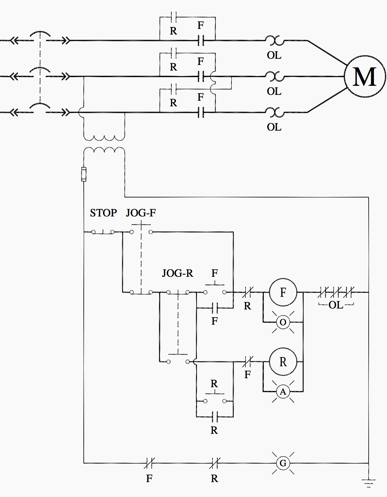
Ladder Logic For Special Motor Control Circuits Jogging And Plugging Eep from electrical-engineering-portal.com • selection of plastic material for high temperature and. Mounting information if multiple contactors are mounted side by side, spacers (ric dist) have to be inserted for the purpose of heat dissipation. Timers were used in many applications in our day to day life.one can see the timers in washing machines,micro ovens etc. The diagram shows an inner section diagram of a relay. The control circuit consists of relays, relay contacts, contactors, timers, counters, etc. There are a lot of applications of this ic, mostly used as vibrators like, astable multivibrator, monostable multivibrator, and bistable multivibrator. An iron core is surrounded by a control coil. Document title electronic relays and controls.
Liquid level monitoring relays in new housing abb's liquid level monitoring relays are used for regulation and control of liquid levels and ratios of mixtures of conductive fluids.
Nema ratings and test values for dc control circuit contacts. Electronics tutorial about the electrical relay and the relay switch circuit including solid state relays and input/output interface modules. Disconnect wires leads from terminals 2 and 4 of fan. Continuous current ratings for common a relay allows circuits to be switched by electrical equipment: Timers were used in many applications in our day to day life.one can see the timers in washing machines,micro ovens etc. Electronic relays and controls news. Timers that have only 1 timing mode (for example. Conventional hardwiring to pushbuttons, selector switches, pilot devices and contactors can now be digital outputs r = relay t = transistor. With help of following timing diagram we can easily understand. The control circuit consists of relays, relay contacts, contactors, timers, counters, etc. There are a lot of applications of this ic, mostly used as vibrators like, astable multivibrator, monostable multivibrator, and bistable multivibrator. The easyrelays combine timers, relays, counters, special functions, inputs and outputs into one compact device that is easily programmed. Vertical power rails and horizontal control rungs. symbols also differ a bit from common electronics notation: